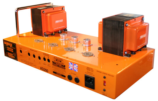
Tim digs into a stock Orange AD200 Bass MK3. He details stripping the amp to its chassis and turning it into a point-to-point handwired amp with high-quality components.
For the past couple of months, I’ve found myself acting as bass player for a new band. It’s been a bit of a change of gears for me as I’m usually playing guitar or lap steel. In playing bass, I found myself with a need for feeding my desire for headroom — a need that can only be satiated with lots of big power tubes and stacks of speakers. I purchased an Orange AD200 bass head with their matching 4×10 and 1×15 bottoms.
In its stock configuration it’s a formidable rig to be sure. I was very impressed with the power, tone and range that it had to offer, even when trying to keep up with a very loud drummer. I played it joyfully for a few months and didn’t have a single complaint. What a happy and content fellow I was… yet… I always have this little nagging voice in the back in my head saying, “what if I changed some components? Sure I’m happy now, but couldn’t I be happier?” And so it always seems to begin with the little nagging voice that I keep listening to against my better judgment. The same voice that often leaves me sitting at my bench, head in hands thinking, why did I start this project? I was so content! WHY?
The concept of changing only a few key components was quickly forgotten once I committed to this project (and had a screwdriver in hand). I gutted the amp to the bare chassis. Out came the printed circuit board (Figure 1) with its board-mounted tube sockets, pots, transformers — everything.
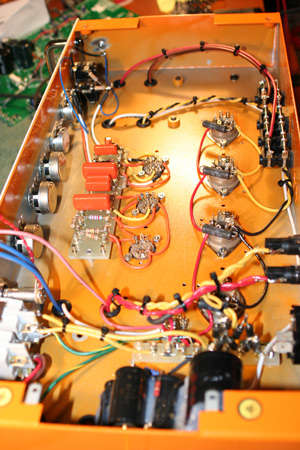
Figure 1: Before gutting.
With the chassis completely stripped, it was time to lay out, measure and drill new holes for the upgraded chassis mounted tube sockets. As the new power tube sockets needed a bit more room than the PCB mounted ones, a Dremel Tool with a coarse sanding drum bit was used to enlarge the holes. Care was taken to make sure that the pin alignment made sense with the lay of the future wires before drilling the mounting holes used to bolt the sockets to the chassis. While I had the drill in hand, I also enlarged the front panel’s pot holes to accommodate the larger upgraded pots that were going to be installed. The placement for the circuit board mounting holes were also located/drilled, as was the location of the ground lugs that were going to be used in the star grounding scheme.
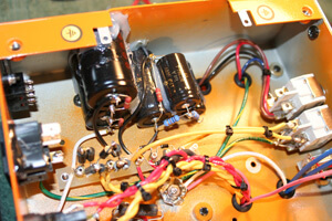
Figure 2: Removing the guts.
One of the most time consuming things for me when building a “one off” amp is the chassis layout. If done properly, it makes the rest of the assembly more of a connect-the-dots type of process. If done in a haphazard and incomplete way, one finds themselves drilling extra holes and routing wires in a way that may not be as professional looking or functional. In high gain designs, a poor layout can lead to excess noise and frustration.
Trying to work within a pre-existing framework is even more of a challenge. It would have been easier to start from scratch with a blank chassis, but I wanted to retain the “Orangeness” of the amp. After all, I am using the original schematic for the project, as it is a fantastic design. I just wanted to upgrade the components and make it a bit more serviceable and rugged.
After mounting the tube sockets (I prefer the Micalex sockets made by Belton) it was now time to select the components to be loaded onto the circuit boards. Unfortunately, this will have to wait for the next installment.
Selection of the parts to be used in a design with a given purpose is an important task. Almost every part in an amplifier makes a difference in the tone — starting with the quality of the AC coming out of the wall, to the power cord, all the way through to the speaker and into the room where the natural acoustics can make or break all of your hard work and tone. Some are pronounced differences, some a bit more subtle. If you add a dozen subtle nuances together, you get a pretty big nuance.
So, how does one wade through the endless amounts of caps, resistors, transformers and other “magical components” available on the market these days? Well, if you’re lucky enough to have the time and financial windfall that we all dream of having, then you can spend your life experimenting, buying and selling great gear without a care in the world. Hopefully, you’re able to develop a relationship with an artist or shop that you can trust and use them as a sounding board. Ultimately, you need to learn to trust your ears. Some of the best sounding amps that I’ve heard have been made with the cheapest, crummiest components. If it sounds right to you, than it is right!
A word of caution: Experimenting can be very fun and rewarding, but it’s easy to get too caught up in the bells and whistles. Don’t forget about the music. I found that when testing some different capacitors in one of my favorite amps that one of the caps sounded much “better” then the other. When I put the “better” sounding cap in and played, I found myself analyzing the sound in every way, from the bass response to the singing highs and, of course, how it felt. When I put the “inferior” cap in, I would start to play, get lost, look at the clock and realize that a half hour had blown by and I didn’t even listen to the cap because I was lost in the music! The “inferior” cap has lived in my amp ever since.
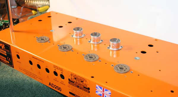
Figure 3: New sockets.
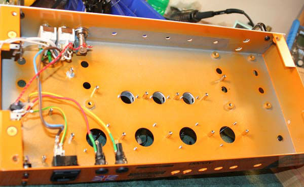
Figure 4: F&T electrolytics power supply caps.
My goal for this project was to “open up” the tone and feel of this already great amp. I wanted tight, slamming bass and open and airy highs with a bit more harmonic interaction. For the power supply caps, I used F&T electrolytics (Figure 4). I like them because of their reasonable size, cost, sound and feel. They are quiet and powerful enough to get good, solid bass without making the amp too fast and therefore not as musical or sweet.
For the coupling caps, I decided on Sprague Orange Drops. I use type 716 as they have a higher quality lead and are a bit more accurate they their 715 brethren. The Orange Drops, while perhaps not as sweet sounding as other choices, have a nice tight bass response with a slightly pinched top end that seems to help with harmonic content and punch. A client described their feel as “walking on packed sand instead of dry loose sand” — perfect for this bass amp.
For resistors, I use different types depending on where they are in the circuit. I don’t like to use carbon comps anywhere that the resistor may be tormented by excessive heat or where it may be prone to inject thermal noise into the signal. I will use them with regularity on the input, for example, but don’t like to use them as plate loads. Of course the brand of resistor has as large an impact as the overall construction. In places where matching and stability are important, I’ll use high-quality metal films.
The pots for this project were a mix of Clarostat Mil Spec. and CTS (CTS because I didn’t have all the values in the Clarostat). I use different types of wire throughout the amps that I build depending on the wire’s purpose. As signal wire, I use certain types of hook-up wire made for the audiophile market. For the B+ and power supply, along with the grounds on the star, I used a high-quality copper multi-strand.
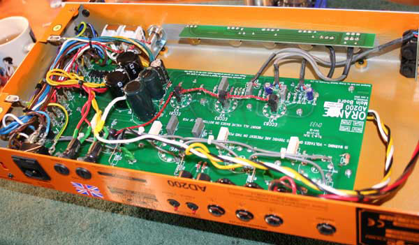
Figure 5: Components installed.
Once all of the parts are selected, they’re laid out and mounted to thick glass component boards (Figure 5) with very sturdy standoffs for ease of mounting. Silicone is applied between caps to create a cushion and help to dampen any unwanted smearing of the signal or microphonics due to rogue vibrations. Paul from Mercury Magnetics sent me a set of beefy transformers that looked quite handsome dressed in their orange end bells.
With the boards made and everything in its place and wired, it was time to fire this creature up and check the voltages at key locations. Using a Variac, voltages are brought up to full power slowly. This is done for a couple of reasons. The first reason is so the electrolytic capacitors in the power supply can form their dielectrics. The second, and perhaps more important, reason is so I can keep an eye on the voltage ratios to make certain that everything is hooked correctly before I install the tubes and risk their lives (and my wallet).
One thing that I appreciate about this design is that Orange took the time (and expense) to design a power transformer and power supply that would deliver 600+ volts to the plates of the power tubes with roughly half of that on the screens. This allows you to get the benefits of high plate voltage (headroom and power) while maintaining a safe operating environment for the power tubes. Now that we’re certain everything is safe and sound, the power tubes (Svetlana “winged c” KT88s) and preamp tubes (mix of NOS RCA and Sylvania) are installed and biased.
Though I’ve been building and modding amps daily for a few decades now, every so often I’m surprised by an end result. With the first strum of the strings, I was floored by the increased headroom, clarity and bell like tones coming out of this powerful amplifier. The change and added versatility in preamp/overdrive section was a pleasant surprise as well. While originally designed as a bass amp, it is fantastic for guitar and pedal steel as well. In retrospect, I’m very glad that I went through the trouble and expense to rebuild this amplifier. It has become my “go to” for almost every application. Long live headroom and power!
Source: https://mercurymagnetics.com/pages/news/PremierGuitar/PremierG-22.htm