
So first things first: an important disclaimer. Modifying an amplifier is serious business, especially when tubes are involved. These amplifiers contain enough voltage inside to kill you, no joke. These kinds of mod kits are intended for people who know what they are doing with electronics. So if you have never used a multi meter (or don’t know what it does) and are not very handy with a soldering iron, these modifications are best left to a professional.
I had heard many good things about the Mercury Magnetics Upgrade Kit for modifying a Epiphone Valve Jr. amplifier. I believe my first encounter with the company was via an ad in Vintage Guitar Magazine (proof advertising actually works!), which prompted a little Internet sleuthing on the subject. My initial searches lead me directly to YouTube, where I found a good collection of demo videos on both the stock Epiphone Valve Jr. and Mercury modified version.
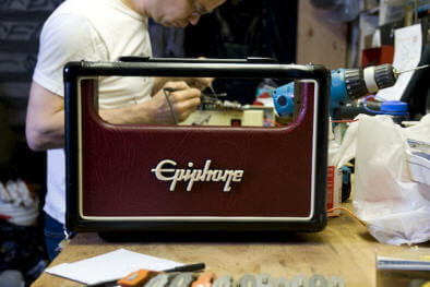
I will say right off the bat that the stock Epiphone (for its price point) is no slouch; it has a good tone for blues and rock and a classic look to it. But after watching some before-and-after videos I was convinced that it would be a worthwhile project.
So with that I purchased two Epiphone Valve Jr. heads and requested a kit from Mercury so we could modify the amp and then see how it stacked up against a stock unit. Phil Manley was the perfect guy to take on this project for GuitarFixation. Phil has a wealth of experience with electronics from building his own fuzz pedals to repairing amplifiers. Phil also has a well-stocked workbench in his garage (yes, a garage in San Francisco — there will never be a time that I don’t covet his garage) that includes a quality soldering iron with adjustable heat and a large assortment of tools, parts, and meters. Again, this is really a project for an intermediate; I would not recommend this to someone who is picking up a soldering iron for the first time.
With all of the parts together I headed over to Phil’s on a foggy San Francisco morning and we began the modification. Pulling the amplifier apart and removing the components was a simple enough task, as Mercury includes a disk with the kit that contains a huge manual and some videos. The only real issue with the instruction manual was that it had almost too much information. The manual is for all three versions of the head (current production is version three) and that made them a little hard to read because the document was referencing all the versions on one diagram. That being said, the instructions are very thorough and it is a good idea for you to read them a few times before you start. [Editor’s Note: Always RTFM, boys!]
Discharging the caps on the main board is a fairly simple task; you just want to ensure that they are totally drained as to avoid any chance of a shock. We didn’t plug in the amp before we started the modification so there was no juice to be found, but if you are going to use the old screw driver technique, you should remember to ground it. A good way to do this is by getting two alligator clips with a wire in between them and connecting one side to the screw driver and the other to a grounded source. It reminded me of when I use to work on tube television: one had to discharge the picture tube with a flat blade screwdriver — POP!
An indispensable tool for this kind of work is a solder sucker that is used to remove hot solder from a board or component. You simply heat the area till it flows and then you load the solder sucker by compressing the spring. Then simply put it over the area in question and hit the button. This will remove most of the solder from the area (you may have to do it twice to get it all), well worth it, as makes adding the new components much easier. You can get one from Radio Shack, but beware their tiny under-$10 model. Be sure to get a half decent one that has a lot of suction to clear away the solder. I recommend the “Edsyn Solder Sucker” it is the one Phil is using in the video. You can get an Edsyn from MarkerTek for about $24 — you can get it HERE.
A Dremel tool will also serve you very well for the modification of the amp. I ended up buying one after Phil had already completed all of the trace cuts on the board (sorry Phil!) The Dremel would have made these cuts worlds easier when compared to using a flat head to scrape away at the trace. If you are not going to use a Dremel then you will want to double check the trace cuts with a meter set to continuity and to ensure that the cuts are 100% or you’re in for some trouble down the road. You will also need a step bit if you decide to do the 6V6 mod, but you could always use a drill and Dremel like we ended up doing when the local hardware store came up flat in the step bit selection (see the video).
So to this point Phil had been working on the amp for a total of five hours, but we had taken a few minutes for lunch and had to make a trip to the hardware store. So in reality I would say this first section took Phil roughly two and a half hours. If you were working alone without someone pointing a camera in your face I think you could have it done in less than two hours. So far the kit is straightforward and easy enough to work on with a reasonably clear set of directions to work from (but be sure to print them in color!) The fun will continue in part two as Phil really gets into the nitty-gritty of this amp mod.
Now on to the installation of the installation of the transformers and Mini-Choke. You want to pay close attention to the directions in terms of how to twist and dress the wires in the chassis. The way you dress your wiring can mean the difference between an amp that is a quiet monster and one that is not even usable. You would not believe the difference a clean, tight wiring job makes on a tube amp!
The re-soldering of the components to the main PCB (printed circuit board) is a fairly simple task, there is not too much that you need to be on the look out for. I had mentioned in part one that you will want an iron that has a variable temperature control; this really comes in handy when you are soldering the resistors and caps. You don’t want to overheat these components as you may damage them and degrade their performance. A high-quality iron is one of the most important tools for this kind of work; it will make all the difference in the world in terms of ease of use and component damage. I also recommend that you look at getting some high quality solder. I use Cardas Quad Eutectic Solder and it is very easy to work with. This solder flows very quickly and has saved me many times from damaging components. The Cardas solder is a tin/lead/silver/copper mix and it is what I use for all of my cable and electronics projects.
Adding the resistors to the 6V6 tube socket is easy, but you will want to ensure that you have a pair of needle nose pliers. It can be tricky to navigate inside the chassis when you have the main board inside, and you’ll want to be extra careful that the iron tip doesn’t hit anything important! You might also notice that when the directions call for you to widen some of the holes on the PCB that the drill bit they call for may not widen out the hole enough. We found that some of the wires were a little too thick for some of the holes, so Phil ended up stepping up to the next bit for some extra wiggle room.
The center tap lead of the power transformer ends up being soldered to the underside of the main PCB board. The directions are not 100% clear on how to go about this, but with a little reading we found that you would need to scrape off some of the coating on the board till you get to the trace below it. For this part, you’ll need to go slowly and may not want to use the Dremel, as you will not want to cut or damage the trace below.
Once you have completed all of the steps on the board, it is helpful to double-check your work to make sure there are no cold solder joints or messy wires. This is the time to do any clean up on the board and neaten the wires. The directions include tips on making the interior nice and neat. Again, stray wires can cause you an unbelievable amount of trouble. You may also want to verify continuity on the trace cuts and the new parts that you soldered.
 The other piece of equipment you’re going to need for this modification is a Variac and if you don’t own one, you’ll need to borrow it. So why exactly do you need one? The Variac will allow you to slowly bring the amplifier up to its operating voltage so you can monitor the amp using a voltmeter to ensure that everything is working correctly. In this case, we pulled the fuse and metered across the terminals to ensure the amplifier was maintaining its correct working voltage. Had the voltage gone past the correct level we could quickly and safely cut the power and not damage the amplifier. If there is an issue you will see the voltage spike well above the recommended level as you are turning the variac up. Also, if you happen to start smelling smoke as you turn the Variac up then you’ll want to immediately kill the power and double check everything.
After we verified that the amplifier was working at the correct voltage it was time to plug in and turn it up! Right from the get go, you could tell that the Mercury Magnetics kit had brought new life into this little amp. The tone was immediately complex and rich, not loud or brutish, but smooth and inviting. There was also the immediate feeling of success; there is just an all around good feeling when you complete a project and hear it working for the first time.